What is this testing for?
When there is a re-arrangement in a SyncE timing signal (i.e. an EEC switches from one reference input to another), that can generate a transient on the output of the EEC. The duration of the transient should be short (less than 15s), and the magnitude should be less than 1000ns. The limit on this transient is described in G.8262 clause 11.1.1, and shown in the following diagram:
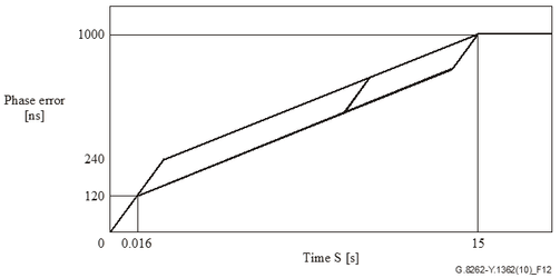
Figure 12/G.8262 – Maximum phase transient at the output due to reference switching for EEC-Option 1
The problem for a T-BC is that it uses the SyncE input as the “tick” of its internal clock, so if that starts “ticking” too fast (or too slow), the T-BC will temporarily have the wrong time. The time error will eventually be corrected by the PTP input, but the transient is so fast compared to the filter bandwidth that nearly the full 1000ns of time error may be coupled into the output of the clock before it is corrected.
Therefore the T-BC is required to reject the phase transient to avoid unacceptably high time error at its output. The SyncE transient response test verifies the T-BC has implemented the rejection properly.
Mitigation Strategies
To reduce the effect of this transient, a T-BC has two possible mitigation strategies. G.8273.2 doesn’t state which one should be used, but it does state that a T-BC should do something.
The two strategies available are either:
When it receives a degraded QL value on the SyncE input, it should stop using the SyncE as its internal “tick”, and use its local quartz oscillator instead.
Or:
When it receives a degraded QL value on the SyncE input, it should keep using the SyncE signal, but turn off the 0.1Hz filter on the PTP input, allowing it to correct the time more quickly.
Each of these strategies has a different characteristic shape to the transient at the output, and these shapes are described in Appendix II of G.8273.2.
T-BC Output if it stops using the SyncE Input
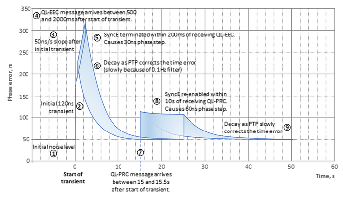
Assumes initial noise level of 50ns (unfiltered).
Transient starts at time=0s, with an initial 120ns phase jump (as described in G.8262).
After the initial transient, the phase ramp of 50ns/s starts (as described in G.8262).
At some point between 500 and 2000ms after the start of the transient, a QL-EEC message arrives, indicating loss of traceability.
Within 200ms of receiving the QL-EEC, the T-BC stops using the SyncE signal. This process takes 200ms, and may cause a phase step of up to 30ns. The shaded area shows the envelope of possible responses.
The T-BC is now relying on its quartz oscillator. The PTP messages slowly correct the time, and the output time error decays, governed by the response of the 0.1Hz filter.
Within 15s of the start of the transient, the EEC re-locks to a traceable reference. It sends a QL-PRC message between 180 and 500ms after this.
The T-BC re-enables the SyncE frequency control within 10s of receiving the QL-PRC message. This causes a phase step of up to 60ns. The shaded area shows the envelope of possible responses.
Subsequent to SyncE being restored, the PTP slowly corrects the time error. The transient response should be finished within 50s of the start.
T-BC Output if it turns off 0.1Hz filter
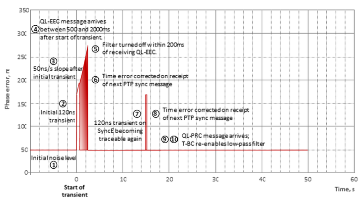
Assumes initial noise level of 50ns (unfiltered).
Transient starts at time=0s, with an initial 120ns phase jump (as described in G.8262).
After the initial transient, the phase ramp of 50ns/s starts (as described in G.8262).
At some point between 500 and 2000ms after the start of the transient, a QL-EEC message arrives, indicating loss of traceability.
Within 200ms of receiving the QL-EEC, the T-BC turns off the low-pass filter.
The time error is corrected on the receipt of the next PTP sync message.
Within 15s of the start of the transient, the EEC re-locks to a traceable reference. There is a transient of up to 120ns on re-lock.
The time error is corrected on the receipt of the next PTP sync message.
The EEC sends a QL-PRC message to indicate it is traceable once more within 180 to 500ms of re-locking.
The T-BC re-enables the low-pass filter within 10s of receiving the QL-PRC message
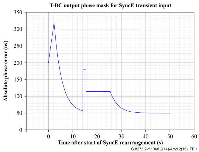
Combined Mask
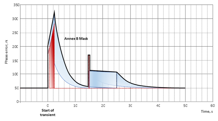
The mask defined in Annex B is the outer envelope of the two responses described above. Therefore it doesn’t matter which technique a T-BC uses, as long as it uses one of them. The purpose of the test is to prove that the T-BC has implemented one of the mitigation strategies. If it has implemented neither, it will fail this test. The combined mask is shown below:
Which Standards define the SyncE Transient Test?
G.8273 Amd2 ( Appendix III) defines the input that should be applied to the device under test. There are three test methods. The most stringent is Method 1.
G.827328273.2 Amd2 defines Annex B defines the maximum allowable phase error (time error) at the output of the DUT when any of the above methods are used to provide the transient input signal pattern.
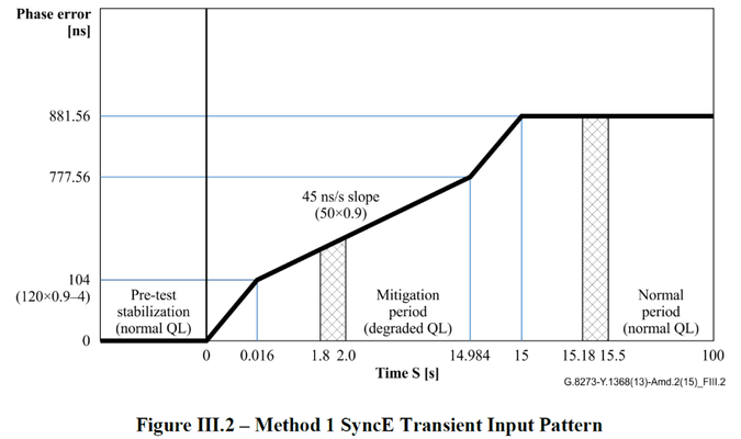
The Method 1 pattern (defined in G.8273 Amd2Appendix III) is described below:
Input an ideal SyncE signal with QL-PRC at interface Y and an ideal IEEE 1588 signal at interface X;
Wait for the T-BC to be fully stabilized;
Start the SyncE transient input signal pattern (e.g., G.8262 transient noise) at interface Y, and send ESMC with QL-EEC at interface Y between 1800 ms and 2000 ms after the start of the transient based on the time of holdover message of G.781.
Wait until 15 seconds (the longest duration before the second transient) after the start of the SyncE transient;
Send ESMC with QL restored to QL-PRC at interface Y after the 15 s mark of step 4, between 180 ms and 500 ms based on the time of the switching message of G.781
Wait 85 seconds and end the test.
This test method can only be achieved under instrument control due to the strict timing requirements. G.8273 Amd2 states Appendix III states "The timing of events in each of the test methods should be accurate to within ±1%".
The output of the device under test while the pattern above is being applied to its input, must meet the mask (defined in G.827328273.2 Amd2Annex B) shown below:
What is the Pre-Test Stabilisation Period?
Prior to beginning the tests, the device under test must be supplied with an ideal SyncE input and an ideal PTP input and the device must have stablised to these ideal inputs. The mask above is applied to the time error measurement and is relative to the stable performance of the device. In other words, whatever the TE performance of the device under ideal conditions, the mask above is applied to the change caused by application of the transient.
See the section describing how the measurement is performed.
How is the measurement performed?
G.827328273.2 Amd2 ( Annex B) states that the measurement is performed "without a measurement filter and should exclude any constant time error. Ideally, the absolute value of unfiltered dTE is desired."
In other words, the measurement is relative to the baseline performance of the device - it is the change caused by the transient that is being measured.
It is not clear what "unfiltered dTE" actually means. Taken literally, unfiltered dTE is just time error. Since this varies over time, it cannot be used directly to adjust subsequent measurements during the transient. However, the intention is clear - constant time error should be excluded. So, in order to measure performance in the presence of a transient, a measure of cTE is required.
Related Articles
| Filter by label (Content by label) | ||||||||||
|---|---|---|---|---|---|---|---|---|---|---|
|
On this page:
| Table of Contents |
|---|