THIS IS A DRAFT. CHANGES MAY BE REQUIRED
The ITU-T G.8263 standard specifies the required performance of packet-based equipment slave clock for frequency (PEC-S-F).
This article describes how to test such a clock using Paragon-X.
Overview
A packet-based slave clock recovers frequency from PTP on an input port. This recovered frequency is then transferred to one or more frequency outputs e.g.
E1
T1
2.048 MHz
SyncE
Hardware and Software Required
Your Paragon-X should have the following options:
Option 250: Master / Slave Emulation
Option 213: SyncE Wander and ESMC (if testing SyncE)
Option 111: 10GbE interface (optional)
You must also have an external frequency reference that is at least as stable as a rubidium.
Connecting your Slave to Paragon-X
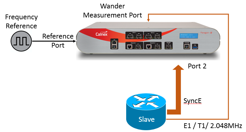
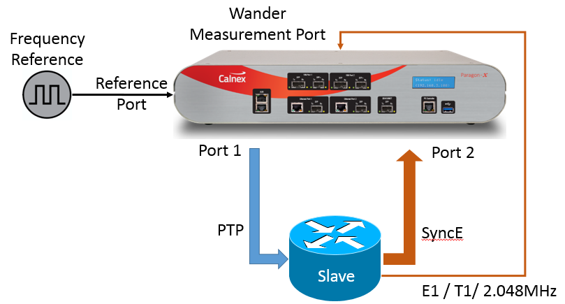
Paragon-X will provide the frequency reference using PTP from the Master port (port 1). This should be connected to the input port on your Slave.
You should connect your output to one of the following ports depending on what you are measuring:
SyncE: Port 2
E1/T1/2M: One of the wander measurement ports on the rear of the Paragon-X.
Configuring Paragon-X for G.8263 Testing
For each test, you may need to configure your test set-up slightly differently. The test set-up is detailed separately for each of the tests below. Once you have configured your test set-up:
Connect to your Paragon-X using Instrument/Connect.
Click the Operating Mode button and select 1588v2 and Enable Master / Slave Emulation in the Operating Mode dialogue.
Click Select Interface and, on the Ethernet tab, configure port 1 for the Line Rate and Interface to be used for the PTP input to the slave.
If testing SyncE, configure port 2 for the Line Rate and Interface carrying the output SyncE
Click the References tab and select the reference Clock Source which you have connected to your Paragon-X.
Click the Master/Slave Emulation (or Master/Slave/GPS Emulation) button to open the Master/Slave Emulation (MSE) Test Setup pane.
Select Slave Test under Test Configuration.
Select G.8265.1 Frequency Profile in the profile selector pull-down. If you need to fine-tune your MSE settings, then click Configure under Device Configuration - this opens the detailed MSE configuration pane.
Section 5.1: Frequency Accuracy
Stimulus | Pass / Fail Criteria | Notes |
|---|---|---|
Free run | +/- 4.6ppm | Test duration is not specified in G.8263. Calnex suggests running for around 1000s |
Measurement Setup
Connect the DUT to Paragon-X as shown in the figure above. The configuration will depend on whether you are testing SyncE or E1/T1/2.048MHz
Ensure that Paragon-X is configured as described in “Configuring Paragon-X for G.8263 Testing”
Measurement Process
Click Measurements and select SyncE Wander, T1 Wander, E1 Wander or 2.048MHz Wander
Click Start Capture
Leave the capture running for 1000s and then click Stop Capture
From the menu bar, click Tools->Calnex Analysis Tool
In the CAT, click View Results and select the TIE tab
In the right-hand pane under Frequency Offset Removal, the frequency offset is displayed. This should be less than +/-4.6ppm.
Section 6.1: Noise Generation
Stimulus | Pass / Fail | Notes |
|---|---|---|
Ideal frequency reference (PTP) | MTIE mask | Test duration is not specified in G.8263. Calnex suggests running for around 10,000s |
Measurement Setup
Connect the DUT to Paragon-X as shown in the figure above. The configuration will depend on whether you are testing SyncE or E1/T1/2.048MHz
Ensure that Paragon-X is configured as described in “Configuring Paragon-X for G.8263 Testing”
Measurement Process
Click Master / Slave Emulation and start the Paragon-X Master Emulation by clicking the green arrow
Allow the DUT some time to lock. The length of time required is dependent on your DUT
Click Measurements and select SyncE Wander, T1 Wander, E1 Wander or 2.048MHz Wander
Click Start Capture
Leave the capture running for 10,000s and then click Stop Capture
From the menu bar, click Tools->Calnex Analysis Tool
In the CAT, click Select Metrics and enable MTIE under Clock Measurements
Click Calculate
Select the MTIE tab and in the right-hand pane under Masks, select G.8263 PEC-S-F Wander Gen Const. Temp.
The Pass / Fail result is indicated in the right-hand pane under Mask Status
Section 7.1: Noise Tolerance
Stimulus | Pass / Fail | Notes |
|---|---|---|
Noise pattern | The PEC-S-F must:
|
Measurement Setup
Connect the DUT to Paragon-X as shown in the figure above. The configuration will depend on whether you are testing SyncE or E1/T1/2.048MHz
Ensure that Paragon-X is configured as described in “Configuring Paragon-X for G.8263 Testing”
Measurement Process
Click Master / Slave Emulation and start the Paragon-X Master Emulation by clicking the green arrow
Allow the DUT some time to lock. The length of time required is dependent on your DUT
Click Measurements and select SyncE Wander, T1 Wander, E1 Wander or 2.048MHz Wander
Click Add Impairments / Delay and then select Delay under Master 1 Tx
Select User defined and click Import. Select one of the Calnex supplied Forward direction PDV noise patterns.
Then select Delay under Master 1 Rx
again select User defined and click Import. Select one of the equivalent Calnex supplied Reverse direction PDV noise pattern.
Click the green arrow to start the impairment
Click Start Capture
Leave the capture running until the impairment has stopped and then click Stop Capture
From the menu bar, click Tools->Calnex Analysis Tool
In the CAT, click Select Metrics and enable MTIE under Clock Measurements
Click Calculate
Select the MTIE tab and in the right-hand pane under Masks, select G.8261.1 PEC-S-F Wander Limit Case 3
The Pass / Fail result is indicated in the right-hand pane under Mask Status
At no point during the test should the DUT have gone into hold-over or have triggered the PTSF- unusable signal.
What tests can I run and why would I choose them
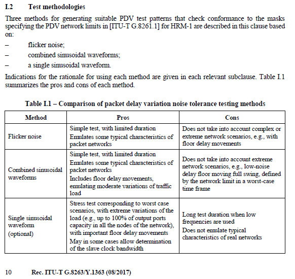
ITU-T G.8263 Appendix I.2 details the Test methodologies as well as a description of what types of tests/patterns could be used

Calnex patterns are available from the Calnex website or under Tools in the Calnex Product FAQ and comprise of the following, where the patterns represent a 64pps rate:
Type | Forward Pattern | Reverse Pattern |
|---|---|---|
Method 1 - Flicker Noise | flicker_gamma_eqn_24h_fwd_to_1588_V2_NEW.cpd | flicker_gamma_eqn_24h_rev_to_1588_V2_NEW.cpd |
Method 2 - Combined sinusoidal waveforms | HRM1_Sum_AvePDVadd_50us_64pps_60ks_fwd_1588_V2_NEW.cpd HRM1_Sum_AvePDVadd_75us_64pps_60ks_fwd_1588_V2_NEW.cpd HRM1_Sum_AvePDVadd_150us_64pps_60ks_fwd_1588_V2_NEW.cpd | HRM1_Sum_AvePDVadd_50us_64pps_60ks_rev_1588_V2_NEW.cpd HRM1_Sum_AvePDVadd_75us_64pps_60ks_rev_1588_V2_NEW.cpd HRM1_Sum_AvePDVadd_150us_64pps_60ks_rev_1588_V2_NEW.cpd |
Method 3 - single sinusoidal waveform | Sin_145us_T1ks_Power-law_-0.5_64pps_64ks_fwd_to_1588_V2_NEW.cpd Sin_145us_T2ks_Power-law_-0.5_64pps_64ks_fwd_to_1588_V2_NEW.cpd Sin_145us_T4ks_Power-law_-0.5_64pps_64ks_fwd_to_1588_V2_NEW.cpd Sin_145us_T8ks_Power-law_-0.5_64pps_64ks_fwd_to_1588_V2_NEW.cpd Sin_145us_T16ks_Power-law_-0.5_64pps_64ks_fwd_to_1588_V2_NEW.cpd Sin_145us_T200s_Power-law_-0.5_64pps_64ks_fwd_to_1588_V2_NEW.cpd Sin_145us_T500s_Power-law_-0.5_64pps_64ks_fwd_to_1588_V2_NEW.cpd Sin_145us_T86400s_Power-law_-0.5_64pps_86400s_fwd_to_1588_V2_NEW.cpd | Sin_145us_T1ks_Power-law_-0.5_64pps_64ks_rev_to_1588_V2_NEW.cpd Sin_145us_T2ks_Power-law_-0.5_64pps_64ks_rev_to_1588_V2_NEW.cpd Sin_145us_T4ks_Power-law_-0.5_64pps_64ks_rev_to_1588_V2_NEW.cpd Sin_145us_T8ks_Power-law_-0.5_64pps_64ks_rev_to_1588_V2_NEW.cpd Sin_145us_T16ks_Power-law_-0.5_64pps_64ks_rev_to_1588_V2_NEW.cpd Sin_145us_T200s_Power-law_-0.5_64pps_64ks_rev_to_1588_V2_NEW.cpd Sin_145us_T500s_Power-law_-0.5_64pps_64ks_rev_to_1588_V2_NEW.cpd Sin_145us_T86400s_Power-law_-0.5_64pps_86400s_rev_to_1588_V2_NEW.cpd |
Section 8.1: Holdover
Stimulus | Pass / Fail | Notes |
|---|---|---|
Loss of reference (following period of lock) | TIE Mask | Test duration is not specified in G.8263. Calnex suggests running for around 10,000s |
Measurement Setup
Connect the DUT to Paragon-X as shown in the figure above. The configuration will depend on whether you are testing SyncE or E1/T1/2.048MHz
Ensure that Paragon-X is configured as described in “Configuring Paragon-X for G.8263 Testing”
Measurement Process
Click Master / Slave Emulation and start the Paragon-X Master Emulation by clicking the green arrow
Allow the DUT some time to lock. The length of time required is dependent on your DUT
Click Measurements and select SyncE Wander, T1 Wander, E1 Wander or 2.048MHz Wander
Click Start Capture
Disconnect the ethernet cable from port 1 of Paragon-X
Leave the capture running for 10,000s and then click Stop Capture
From the menu bar, click Tools->Calnex Analysis Tool
In the CAT, select the TIE tab and in the right-hand pane under Masks, select G.8263 PEC-S-F Long-Term Holdover Const. Temp.
Adjust the Data Analysis Range so that the mask is aligned with the point at which the slave begins to go into hold-over. This can either be done by moving the vertical range bars on the graph or by typing the range in the right-hand pane under Parameters
The Pass / Fail result is indicated in the right-hand pane under Mask Status
| Table of Contents |
|---|