
1. Standards aimed at delivering frequency to better than 50ppb
On this page:
Main use case: 2G, 3G and 4G cellular mobile radio using Frequency Division Duplexing, FDD
The major use case is for frequency synchronisation of cellular mobile radio basestations. The GSM (2G), UMTS (3G) and LTE (4G) standards were all originally based on Frequency Division Duplexing (FDD) of the radio (i.e. they operated upstream and downstream transmissions simultaneously on different frequencies). The basestations require accurate frequency synchronisation to ensure the carrier frequency of the radio signal is correct.
Originally, 2G and early 3G mobile radio basestations were connected using TDM networks (e.g. E1 or T1 circuits). These networks used a stable, physical layer frequency, and the radio basestations were able to use this frequency to control their radios.
When high-speed data arrived in 3G and 4G, the network connections changed to packet-based networks such as Ethernet. Therefore there was a need to replace the TDM-based physical layer synchronisation with another method.
Method 1a: Synchronous Ethernet (SyncE)
SyncE is built on the well-established concepts and standards that existed for SDH networks. It involves locking the Ethernet physical layer frequency to an incoming reference frequency. This provides a very stable frequency to the end application (e.g. a cellular basestation), but all the equipment in the synchronisation chain must support SyncE.
The performance specification for the Ethernet Equipment Clock was made identical to the SDH Equipment Clock (SEC, defined in G.813). This enables the EEC and SEC to be interchangeable, simplifying the changeover from SDH to Ethernet-based deployment. Most recently, the standard has been extended to also include the OTN Equipment Clock (OEC), with the same basic performance specification.
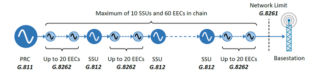
The diagram below shows the synchronisation reference chain, with up to 60 EECs in a chain from the Primary Reference Clock (PRC) to the end equipment, i.e. the cellular basestation. The network limit for the chain is defined in G.8261, and is the same as the PDH synchronisation network limit defined in G.823, such that the synchronisation is
SyncE also has a status messaging channel (similar to the Synchronisation Status Messaging, SSM, defined for SDH equipment). This is called the Ethernet Synchronisation Message Channel (ESMC), defined in G.8264, and is backwards-compatible with SSM, allowing for inter-operation with existing SDH synchronisation chains. These messages are only used for the “control plane” of SyncE, the actual frequency reference is distributed through the physical clocking of the bits on the SyncE interfaces.
| Concepts / Overview | CX3002 | Jitter and Wander in SyncE: Testing Jitter and Wander to ITU-T Standards |
|---|---|---|
| CX8010 | The importance of measuring wander on high speed interfaces | |
| General Information | G.8260 | Definitions and Terminology for Synchronisation in Packet Networks |
| Clock Specifications | G.811 | Primary Reference Clock (PRC) Specification |
| G.812 | Synchronisation Supply Unit (SSU) Specification | |
| G.8262 | Ethernet Equipment Clock (EEC) Specification | |
| Network Specifications | G.8261 | SyncE Network Limits (clause 9.2.1) |
| Protocol Specifications | G.8264 | Ethernet Synchronisation Messaging Channel (ESMC) (clause 11) |
| Test Guide | CX5018 | Sentinel Field Test Plan for Frequency Synchronisation using PTP |
| CX5001 | G.8262 SyncE conformance testing: Proving SyncE compliance to ITU-T G.8262 using Paragon-X | |
| CX5026 | Testing EECs to ITU-T G.8262 using Paragon-100G |
Method 1b: Precision Time Protocol (PTP)
The second method is to use the Precision Time Protocol, PTP, as the method to distribute frequency out to the basestations. This is a packet-based time distribution protocol, and has the advantage that it works over existing networks of switches and routers without having to upgrade them to support SyncE. For many mobile operators, this is required as they have to use third-party access networks that haven’t necessarily deployed SyncE.
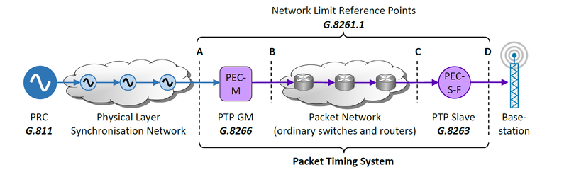
The downside is that the packet delay variation (PDV) created by queuing mechanisms within these devices affects the stability of the frequency. This PDV must be limited in order to guarantee the output frequency will be sufficiently stable. The network limits at various points in the network are defined in G.8261.1.
The diagram below shows the application of this method. The original frequency comes from a PRC via a physical layer synchronisation network to the PTP Grandmaster (GM). In some instances, the GM might also be included in the same piece of equipment as the PRC, removing the need for the physical layer synchronisation network. This is very common with GNSS-based PRCs.
The GM encodes the frequency into packet streams using PTP, and sends it over the packet network to the PTP Slave clock. The packet network consists of ordinary switches and/or routers, with no special adaptation for handling PTP messages. The slave clock is responsible for converting the packet stream back into a frequency for transmission over a physical layer clock to the basestation.
| Concepts / Overview | ||
|---|---|---|
| General Information | G.8260 | Definitions and Terminology for Synchronisation in Packet Networks |
| G.8265 | Architecture and requirements for packet-based frequency delivery | |
| Clock Specifications | G.811 | Primary Reference Clock (PRC) Specification |
| G.8266 | PTP Frequency Grandmaster Clock Specification (Packet Equipment Clock – Master, PEC-M) | |
| G.8263 | PTP Frequency Slave Clock Specification (Packet Equipment Clock – Slave – Frequency, PEC-S-F) | |
| Network Specifications | G.8261.1 | PTP Network Limits |
| Protocol Specifications | G.8265.1 | PTP Telecom Profile for Frequency |
| IEEE1588 | Precision Time Protocol | |
| Test Guide | CX5018 | Sentinel Field Test Plan for Frequency Synchronisation using PTP |