
2. Standards aimed at delivering time and phase to better than 1.5us
On this page:
Main use case: 3G, 4G and 5G cellular mobile radio using Time Division Duplexing, TDD
Some UMTS and LTE cellular networks use Time Division Duplexing (TDD) instead of FDD. This is where the upstream and downstream data are transmitted on the same carrier frequency, but in different time slots, rather than simultaneously. TDD can be more efficient, especially if the traffic is asymmetric (e.g. higher download traffic than upload), as the upstream and downstream traffic can be allocated different data rates by varying the number of time slots allocated to each.
In TDD networks, neighbouring basestations must be synchronised in time to prevent them interfering with each other. This is achieved by synchronising them all to a central time reference clock. The required accuracy is better than ±1.5μs relative to the central clock.
Method 2a: PTP and SyncE, with a BC or TC at every node in the network
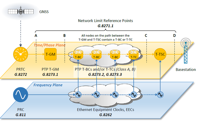
The accuracy of a PTP system can be improved by including either a Boundary Clock (BC) or Transparent Clock (TC) at each node in the network. These devices remove the PDV associated with queuing mechanisms in the switching fabric. The accuracy can be further improved by using SyncE to stabilise the frequency at each node. Together, this is known as “full timing support” (FTS), where every node in the network must support both SyncE and either a BC or TC function.
In this solution, frequency and time are transmitted separately. The “frequency plane” consists of physical layer synchronisation, e.g. SyncE, feeding up to the “time and phase plane” which uses PTP. The management and organisation of each plane is normally separate, meaning it is not necessary for the SyncE and PTP signals to share the same path.
These two planes can be seen in the diagram below. The time comes from a Primary Reference Time Clock, which is most implementations is a GNSS-based time receiver, often containing an integrated PTP GM function. The GM encodes the time reference into packet streams using PTP, and sends it over the packet network to the PTP Slave clock. To deliver time, a bi-directional transfer of packets is required between the GM and the slave. In addition, every switch and/or router contains a BC or TC function to help remove the PDV generated by the network. The stability of each of these functions is further enhanced by the frequency plane based on SyncE.
| Concepts / Overview | CX6001 | Testing a T-BC to ITU-T G.8273.2 |
|---|---|---|
| CX6002 | Measuring Time Error Transfer of G.8273.2 T-BCs | |
| General Information | G.8260 | Definitions and Terminology for Synchronisation in Packet Networks |
| G.8275 | Architecture and requirements for packet-based time and phase distribution | |
| Clock Specifications | G.811 | Primary Reference Clock (PRC) Specification |
| G.8262 | Ethernet Equipment Clock (EEC) Specification | |
| G.8272 | Primary Reference Time Clock (PRTC) Specification (Class A) | |
| G.8273.1 | PTP Telecom Grandmaster (T-GM) Specification (under development) | |
| G.8273.2 | PTP Telecom Boundary Clock (T-BC) and Time Slave Clock (T-TSC) Specification (Class A, B) | |
| G.8273.3 | PTP Telecom Transparent Clock (T-TC) Specification (Class A, B) | |
| Network Specifications | G.8261 | SyncE Network Limits (clause 9.2.1) |
| G.8271.1 | PTP Network Limits | |
| Protocol Specifications | G.8264 | Ethernet Synchronisation Messaging Channel (ESMC) (clause 11) |
| G.8275.1 | PTP Telecom Profile for Time (Full Timing Support) | |
| IEEE1588 | Precision Time Protocol | |
| Test Guide | CX5008 | T-BC Time Error - Testing Boundary Clocks to ITU-T G.8273.2 using Paragon-X |
| CX3003 | PTP Time Error for T-BC: Testing Boundary Clocks to ITU-T G.8273.2 using Paragon-100G | |
| CX5020 | T-TSC Time Error: Testing Time Slave Clocks to ITU-T G.8273.2 using Paragon-X | |
| CX5021 | T-TC Time Error: Testing Transparent Clocks to ITU-T G.8273.2 using Paragon-X |
Method 2b: GNSS Receivers with PTP as a backup
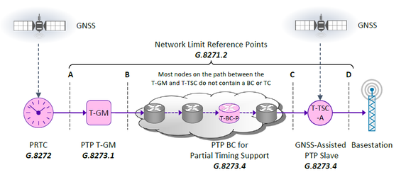
In some situations, the time and phase reference may be distributed via GNSS direct to the cell site, or a location very close to it. The issue here is that the GNSS may fail under some circumstances. Actual GNSS system failures are rare (albeit not totally unknown), but physical failures such as antenna malfunctions, or local interference are more common. Therefore it is required to have a backup system to maintain time and frequency in the event of losing the GNSS reference.
It might not be viable for the operator to deploy GNSS receivers at the cell site, and upgrade the existing network to provide PTP and SyncE support. However, it is possible to distribute time using PTP over existing networks that do not have PTP or SyncE support, similar to the frequency distribution method described in 1b. The number of switches and routers that can be passed through are limited because of the PDV generated by those networks, and also because of network asymmetry – the tendency for the delay in each direction to be different.
However, as the end slave clock has a GNSS reference most of the time, the asymmetry may be measured and compensated for. Secondly, the PDV can be monitored to assess whether the time can be maintained accurately in the event of a GNSS failure. This method is known as “assisted partial timing support”, APTS.
Some devices on the path may use a BC function to “clean up” the PDV and regenerate the PTP stream. It should be noted that such a BC function is not the same kind of BC as defined for full timing support. This is new type of BC specifically designed to filter out PDV generated by queuing behaviour, and is under development in G.8273.4. It is not possible to use a G.8273.2 T-BC function in an APTS or PTS network.
| Concepts / Overview | ||
|---|---|---|
| General Information | G.8260 | Definitions and Terminology for Synchronisation in Packet Networks |
| G.8275 | Architecture and requirements for packet-based time and phase distribution | |
| Clock Specifications | G.8272 | Primary Reference Time Clock (PRTC) Specification (Class A) |
| G.8273.1 | PTP Telecom Grandmaster (T-GM) Specification (under development) | |
| G.8273.4 | Assisted Partial Timing Support Clock (T-TSC-A) Specification (under development) | |
| Network Specifications | G.8271.2 | Network Limits |
| Protocol Specifications | G.8275.2 | PTP Telecom Profile for Time (Partial Timing Support) |
| IEEE1588 | Precision Time Protocol | |
| Test Guide | CX4005 | Sentinel Field Test Plan for TDD-LTE/LTE-A Synchronisation in Systems using Assisted Partial Timing Support and Partial Timing Support |
Method 2c: PTP
The third method is to use the packet-based protocol, PTP, as the sole method to distribute time and phase out to the basestations. This will work over small existing networks of switches and routers without having to upgrade them to support PTP and SyncE. For many mobile operators, this is required as they have to use third-party access networks that haven’t necessarily deployed SyncE. This is known as “partial timing support” (PTS), indicating that not all of the switches and routers may have PTP or SyncE support.
In this situation, there is no GNSS reference available at the end location, so any asymmetry and PDV in the network must be bounded to keep the synchronisation accuracy within limits.

| Concepts / Overview | ||
|---|---|---|
| General Information | G.8260 | Definitions and Terminology for Synchronisation in Packet Networks |
| G.8275 | Architecture and requirements for packet-based time and phase distribution | |
| Clock Specifications | G.8272 | Primary Reference Time Clock (PRTC) Specification (Class A) |
| G.8273.1 | PTP Telecom Grandmaster (T-GM) Specification (under development) | |
| G.8273.4 | Assisted Partial Timing Support Clock (T-TSC-A) Specification (under development) | |
| Network Specifications | G.8271.2 | Network Limits |
| Protocol Specifications | G.8275.2 | PTP Telecom Profile for Time (Partial Timing Support) |
| IEEE1588 | Precision Time Protocol | |
| Test Guide | CX4005 | Sentinel Field Test Plan for TDD-LTE/LTE-A Synchronisation in Systems using Assisted Partial Timing Support and Partial Timing Support |