
G.8273.2 (7.3.1, 7.3.2): Noise Transfer
Appendix VI is not an integral part of the standard. What are the implications of this?
Clauses 7.3.1 and 7.3.2 provide only a limited definition of the characteristics of the filters in a clock. Only the bandwidth and a gain-peaking limit in the pass-band are specified. The gain-peaking limit is 0.1dB for PTP-XXX noise transfer and 0.2dB for SyncE-XXX noise transfer.
In particular, Clauses 7.3.1 and 7.3.2 do not define the filter roll-off or the maximum attenuation in the pass-band.
Appendix VI, makes a number of recommendations regarding the filter characteristics. These recommendations are based on a first-order filter (20dB/decade roll-off) with a maximum pass-band attenuation of 3dB.
Since Clauses 7.3.1 and 7.3.2 do not define the filter characteristics fully and Appendix VI is not an integral part of the standard, you may choose to test only the pass-band gain-peaking.
If you decide that you only want to test gain-peaking in the pass-band, then the least squares estimator and limit checking should both be disabled (see below).
Once the limit checking and LSQ have been disabled, then the user must apply their own judgment to determine whether their device is operating correctly (because Clauses 7.3.1 and 7.3.2 do not explicitly define how to deal with DUT noise generation).
Paragon-neo and Paragon-100G
Disable the least squares estimator by de-selecting the Filter checkbox in the CAT on the Noise Transfer tab.
Disable the limit checking by de-selecting the Limit check box in CAT
Paragon-X (Enhanced Noise Transfer script)
Run the script with:
Filter NONE
LimitsEnabled FALSE
The ENT script, Paragon-100G and Paragon-neo test use a Least Squares Estimation technique when making Noise Transfer measurements. Could other methods be used?
G.8273.2 Appendix VI mentions 4 different techniques that could be used for making Noise Transfer measurements. These are:
Allow up to +/-50ns for noise generation
Measure the actual noise generation of the T-BC and use this as the allowance
Use a least-squares estimation algorithm to remove the noise generation of the clock and estimate the output amplitude of the sine wave test tone
Use a pulse-amplitude modulation method to re-construct the original signal. This involves taking a Fourier transform of then output to recover the tone frequency and its amplitude
Taking each of these in turn:
(1) An allowance of +/-50ns on test limits (N=50) with an input amplitude of 200ns / 250ns is a poor test of the device. In general, we would expect much better performance than this and other techniques allow for more rigourous testing of the DUT.
Should customers wish to use these wide limits and get a pass / fail result, the measured values returned from the script or Paragon-neo/100G (CAT) can be compared against the user's limits to determine the pass / fail result. In this case, the least squares estimation and limits should be disabled. For Paragon-neo/100G, this can be done using the CAT; for Paragon-X, this is not currently supported by the ENT script - this capability will be added in the next release.
(2) Calnex did consider using this technique. However, it relies on noise effects being additive (which is not always the case)
(4) This approach could be adopted by the Paragon-X script and Paragon-neo/100G test. However, it would involve implementing and testing an FFT (DFT). It is unknown whether the performance of such an algorithm would be significantly better than Least Squares.
The ability of the least squares method to estimate the pk-pk amplitude of a tone (or alias frequencies) in the presence of white noise has been evaluated and has been shown to be sufficiently accurate for use in the Noise Transfer test.
Why are T4 Time Error results used and not T1 or 2Way?
The frequencies used in the noise transfer test are carefully selected so that measurements can be made correctly at 16Hz (16 pkts/sec).
Since the Sync packet rate from the DUT cannot be guaranteed, the T4 time error result is used instead. The Paragon instrument tightly controls packet transmission time and so the sample rate will be correct.
Note: the same argument applies to using the 2Way results
Why is there an additional 10ns/25ns allowed in the limits?
Appendix VI describes the rationale used to propose amplitudes, frequencies and limits for Noise Transfer.
The PTP to PTP and 1pps limits have been determined using the following process:
- Clause 7.3.1 only loosely defines the expected filter characteristic. It defines the following characteristics:
- Low pass filter with a bandwidth between 0.05Hz and 0.1Hz
- Maximum gain peaking in the pass-band of 0.1dB
Appendix VI.4 further recommends these additional characteristics:
- The low pass filter should have an attenuation greater than or equal to that of a first-order, -20dB/decade filter
- The maximum attenuation in the pass-band should be 3dB
- The attenuation at 0.1Hz should be at least 3dB
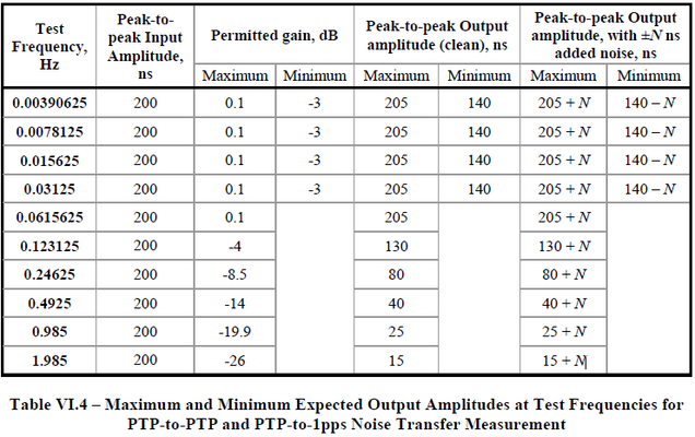
At each input frequency/amplitude, the filter characteristic above determines the "perfect" (noise-free) output amplitude. This is shown in the column labelled "Peak-to-peak Output amplitude (clean)" in Table VI.4 (also shown below). Maximum figures are rounded up to the nearest 5ns, while minimum figures are rounded down, i.e. the permitted gain is applied to the input amplitude and the corresponding expected output amplitude is rounded to the nearest 5ns up or down respectively.
Since the DUT will add noise, these "clean" limits cannot be used for testing. Some allowance needs to be made for the amount of noise generated by the DUT, so an allowance (N) is added to the limits - this is shown in the column labelled "Peak-to-peak Output amplitude, with +/-N ns added noise" in Table VI.4.
- Appendix VI makes no suggestions as to the value of N, but suggests four methods that could be used to account for the noise generation of the DUT. Some methods are more accurate than others, hence the value of N may vary dependent on the method used. The Paragon-X ENT script and the Paragon-neo/100G both use a least-squares estimation algorithm (the third method) to remove noise and estimate the output amplitude of the test tone.
- The choice of "N" is determined by the ability of the least-squares estimator to measure the peak-to-peak amplitude of the output tone in conjunction with the measurement accuracy of the instrument (Paragon-X and Paragon-100G). "N" must be large enough to cope with the measurement uncertainty but small enough to ensure that the DUT is meeting the requirements of the standard. Evaluation of the least-squares algorithm in conjunction with the Paragon-X and Paragon-100G has shown that N=10ns provides a balance between the ability to measure accurately and giving confidence that the DUT is meeting its requirements.
- The SyncE to PTP and 1PPS limits are set using a similar rationale to the above. However, in this case a value of N=25ns has been used. The extra 15ns takes account of the noise added to PTP due to the application of SyncE wander.
Can the value of N be changed?
In the Paragon-X Enhanced Noise Transfer script and Paragon-neo/100G, the value of N is fixed. If the user wishes to test performance to their own limits, then Calnex do not provide a way to change limits and get a pass / fail result.
Should customers wish to use their own limits, the measured values returned from ENT / CAT can be compared against the user's limits to determine the pass / fail result. In this case, the least squares estimation and limit checking should be disabled (see above).
According to G.8273.2 Appendix VI, the Least Squares Estimation method works for white noise. The accuracy of this method with other types noise is for further study. What does this mean for the Noise Transfer test?
On noise types, the exact statement in Appendix VI is:
3) Use a least-squares estimation algorithm to remove the noise generation of the clock, and estimate the output amplitude of the sine wave test tone. This is capable of estimating the amplitude to a reasonable precision with a good level of confidence, provided the added noise is white phase modulation. The accuracy of this method when the added noise has different characteristics (e.g., random walk, other power-law noise types, or sinusoidal noise) is for further study.
In this statement, including random-walk does not make sense because no locked clock can produce random-walk noise. An oscillator might, but not a clock, since the time error would constantly grow for random-walk noise. Therefore it would fail the noise generation limits.
“Other power-law noise types” – the least-squares algorithm was tested on flicker as well as white noise.
Sinusoidal noise (or other periodic noise such as saw-tooth noise) are the problem types. If the noise has a regular period that is closely related to the noise stimulus period then LSQ can’t filter this out. The LSQ will remove the random noise components, but the regular periodic noise components are not removed. This will result in a higher measurement result than should be the case.
For PTP-XXX noise transfer, the DUT should not be generating such noise in the first place and so investigation of the DUT performance would be required.
For SyncE-XXX noise transfer, periodic noise may be present on the output because any SyncE wander will affect the PTP from Paragon and may also be generated on the PTP/1PPS outputs from the DUT. This effect is covered by N=25ns for SyncE-XXX noise transfer.
Related Articles
On this page: