
Paragon-X: How to perform Time of Day (ToD) measurements
Paragon-X can capture and generate CCSA, NMEA and G.8271 ToD data. This article explains the configuration steps required to do so.
Instructions
ToD output from P-X is on the rear DB9 connector, port 17 in the below diagram:
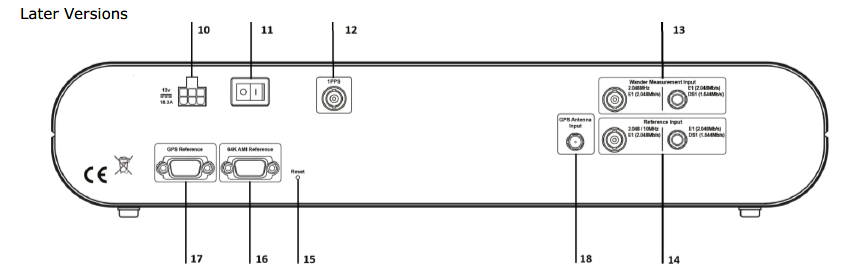
The pinout for this port is
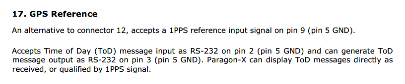
Because this is a serial input, it’s important to configure the port to match the expected ToD input. This is done in the Setup Interfaces window:
The baud rate menu is shown here as this will likely require changing from the default, and will result in garbage being displayed if it doesn’t match the input rate.
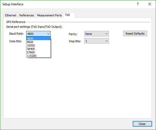
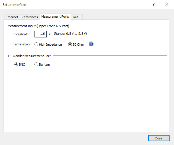
The Measurement Ports tab in this window also allows the configuration of the 1PPS input. Ensure that the appropriate input termination is set to match your DUT output, and that the voltage threshold is about half the 1PPS voltage:
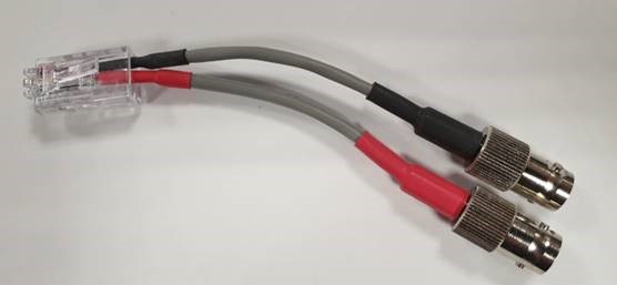
The 1PPS measurement port is the ‘Upper Aux port’ on the front of the P-X. You can use the provided BNC to RJ48 adapter cables to connect a BNC cable to this (use the black BNC connection):
Configuration of the Time of Day generation is enabled by ticking the GPS Emulation checkbox in the MSE setup page:
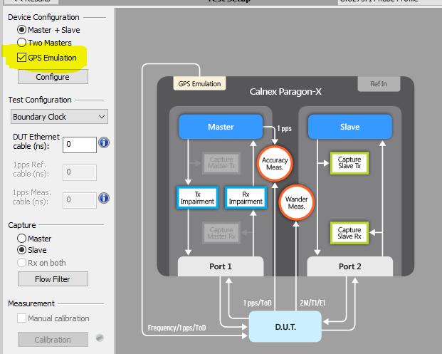
Which then enables the config options (accessed by clicking the ‘Configure’ button below the GPS Emulation checkbox):
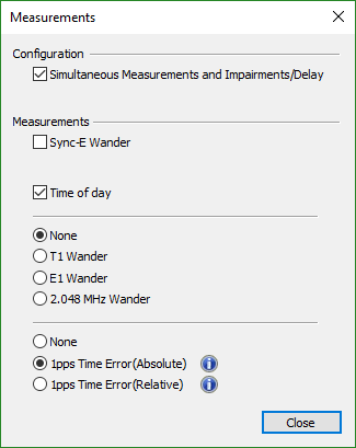
To enable a ToD measurement, use the Measurements button to enable a 1PPS measurement, which will then enable the ToD checkbox:
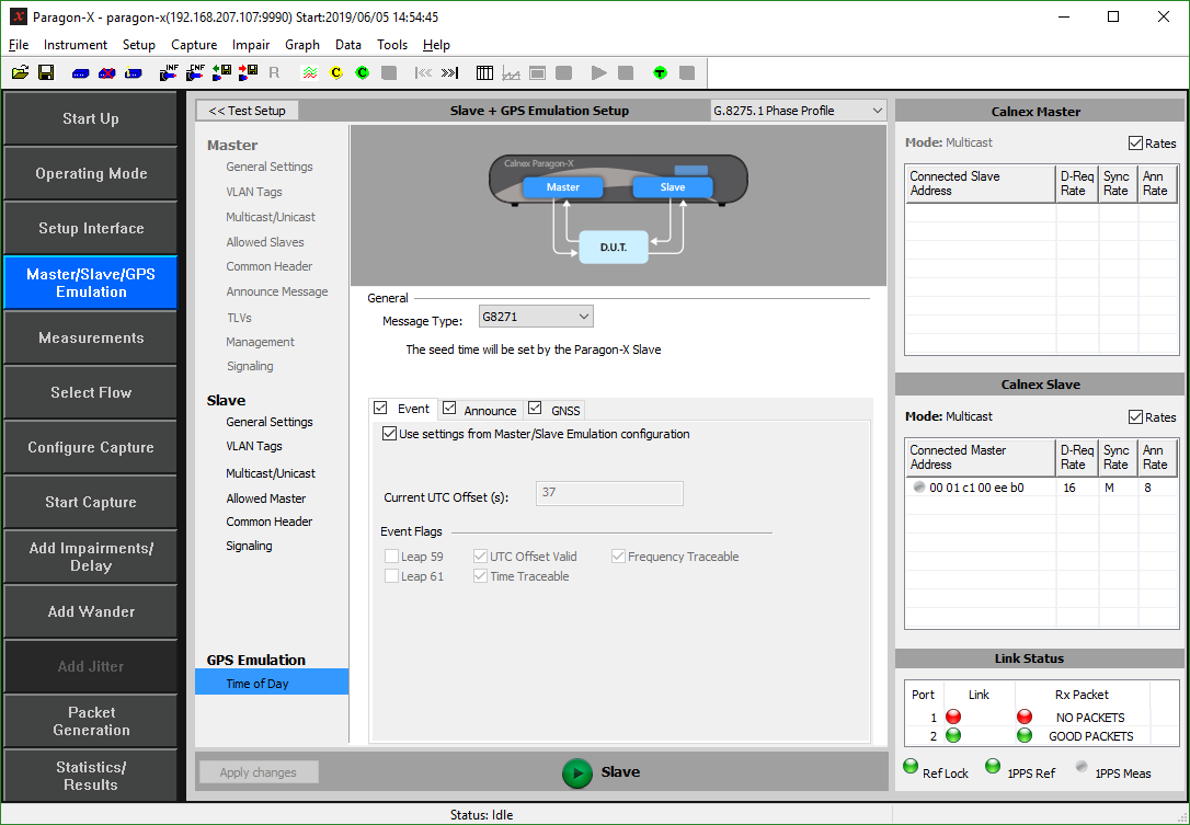
This will then capture the ToD measurement alongside the 1PPS data. To configure the ToD capture, use the Configure Capture button:
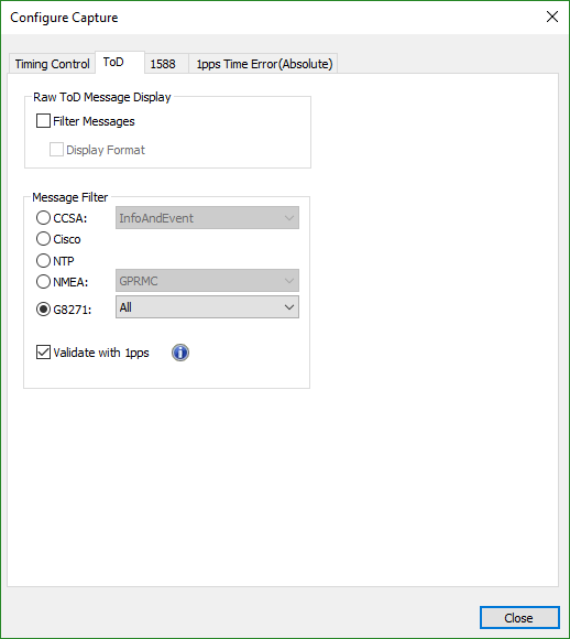
to select the appropriate format and message types.
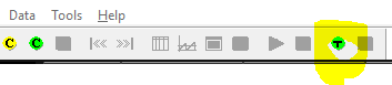
Once this is all configured and the ToD input is active, you can do a ‘raw ToD capture’ to confirm the ToD input is correctly detected. Use the green T button at the top of the P-X GUI to start this capture:
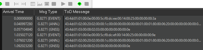
And assuming a valid 1PPS and ToD input is received, the raw data will be displayed below. The red square (which will be to the right of the green T) is used to stop this capture.
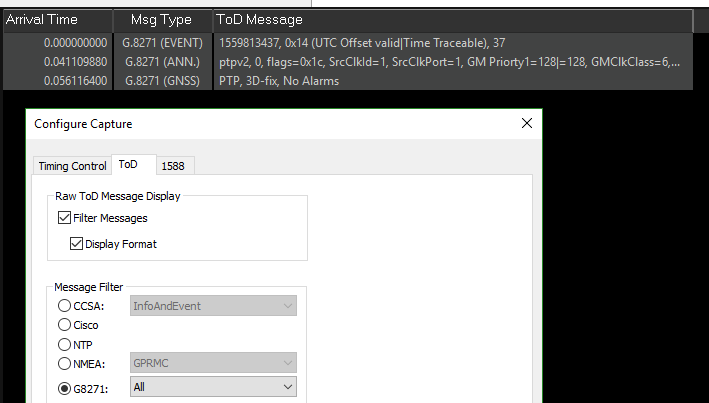
Using the Configure Capture button, you can filter this data to show only the format of interest (if there was more than one being received, which is unlikely), and checking the Display Format button will decode some of the data into human-readable format:
Once you’re happy this is all functioning correctly, starting a capture in the usual way with the Start Capture button will capture your ToD and 1PPS data along with the PTP.
You can select which capture data is displayed using the dropdown menu on the P-X GUI:
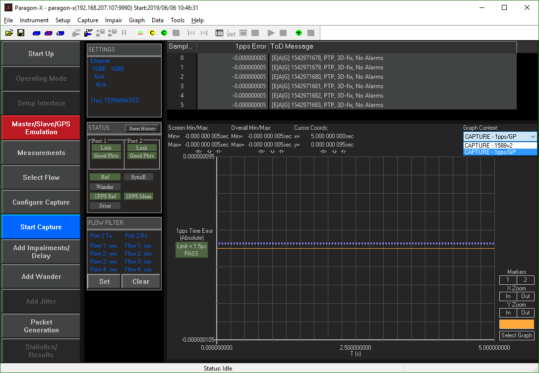
And can send the displayed data to CAT for further analysis as usual. Any vertical red lines on the 1PPS graph indicate missing pulses, so should be investigated and resolved for a valid measurement.
Related articles