
G.8262: Wander Tolerance and Transfer for Option II Clocks
Introduction
G.8262 defines wander tolerance and transfer for Option II clocks in terms of TDEV masks at the input and output of the clock. This is different from Option I clocks, which define the tolerance in terms of frequencies and amplitudes. The motivation is the same in both cases however, to prove:
- that a clock is able to handle a defined amount of wander at its input
- that the wander at the input is filtered using the correct filter bandwidth and type, and that the clock does not amplify any wander due to gain peaking in the filter
The different specification methods comes down to the fact that Option I and Option II clocks were originally specified in different standards bodies: Option I came from ETSI, the European standards institute, and Option II from ANSI in North America.
The Option II method presents some practical difficulties for the following reasons:
- defining wander tolerance using TDEV only limits the RMS amplitude of the input waveform, but not the peak value. Therefore if the wander noise has a low peak to RMS ratio, it may not adequately test the peak wander tolerance capability of the clock.
- for wander transfer, the gain of the clock in the passband is limited to 2% by the output mask. TDEV wander generation is difficult to generate accurately, and O.174 (the test equipment standard for SyncE clock testers) only defines that TDEV wander must be generated to 20% accuracy. This inaccuracy swamps the gain peaking allowance, requiring the TDEV noise generated at the clock input to be carefully measured and calibrated prior to using for wander transfer
- In fact, G.8262 states that “The purpose of these masks is to ensure that the maximum bandwidth of an EEC is 0.1 Hz. These masks should not be used to verify phase gain peaking”
For this reason, Appendix V of G.8262 suggests that the tone method used for Option I clocks may be used to test Option II clocks. This article suggests tone frequencies and amplitudes to be used in wander tolerance and transfer testing.
Peak Wander Tolerance for G.8262 Option II Clocks
G.8262 itself only defines the wander tolerance of Option II clocks in terms of TDEV. There is no peak wander tolerance specification, unlike Option I which has an MTIE mask (Table 7/Figure 5). Similarly, there is no MTIE network limit specified in G.8261 for Option II SyncE signals.
SyncE “borrowed” the specification of the SEC from G.813 (clock spec) and G.824 (network limits), and G.824 does specify the maximum wander on a 1544 kbit/s reference signal in clause 6.2.2 (see Figure 3 from G.824, reproduced below). It is therefore proposed that since in all other respects the SyncE clock has identical performance to the SEC, these limits are also adopted for the SyncE Option II clock.
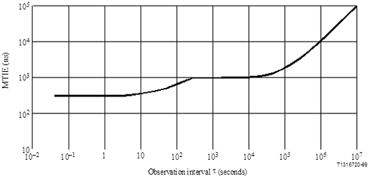
Figure 3 / G.824 - MTIE limit for 1544kbits/s reference signals
Generating a set of tones for Wander Tolerance Testing
Using the MTIE mask defined in G.824, a tolerance mask for clock testing can be produced as follows. For each observation interval τ in the MTIE mask, a tone can be generated at a frequency equal to 1/ (pt). The amplitude of that tone is equal to the height of the MTIE mask at that observation interval.
It is proposed to use two points per decade, with an additional tone to hit the corner point of the mask at 280s observation interval. The maximum observation interval is 1000s, since the TDEV masks only go up to 1000s.
The set of tones resulting from this calculation is shown in the table below:
Observation interval, | MTIE (ns) | Tone Frequency | Tone Amplitude |
|---|---|---|---|
0.1 | 300 | 3.2 | 300 |
1 | 303 | 0.32 | 303 |
10 | 325 | 0.032 | 325 |
100 | 550 | 0.0032 | 550 |
280 | 1000 | 0.0011 | 1000 |
1000 | 1007 | 0.00032 | 1007 |
Wander Transfer Testing
Wander transfer testing is carried out by generating a set of tones at the input, and measuring the amplitude at the output. In the stop-band, this should be attenuated, while in the passband, the tones should be passed through without modification or amplification. G.8262 defines the maximum gain peaking in the passband should be 0.2dB, with a maximum bandwidth of 0.1Hz.
G.8262 does not state the type of filter for Option II, but it is assumed here to be at least a first order filter with 20dB/decade attenuation above the maximum bandwidth. There is no minimum bandwidth specified, so there is no minimum gain requirement.
A similar set of tones can be used in the wander transfer as were used for wander tolerance. In the table below, the set of tones is augmented to provide two tones per decade. This provides more resolution on the shape of the frequency response.
The tone amplitudes can be taken from the G.824 network limit as described above. The input port should be capable of tolerating this magnitude of input, and secondly, the gain peaking is so small, it is more accurate to measure it on the maximum possible input amplitude.
An allowance of 20ns is used for noise generation of the clock. This is approximately 2% of the output amplitude in the pass band (1000ns). The first 50s of each test is ignored to allow time for the 0.1Hz filter in the device under test to settle.
The attenuation and maximum output amplitude for each of the tones is shown in the table below:
Tone Frequency | Input Tone Amplitude | Test Time | Max. Gain | Maximum Output Tone Amplitude |
|---|---|---|---|---|
3.2 | 300 | 480 | -30.1 | 30 |
1 | 301 | 150 | -20.0 | 50 |
0.32 | 303 | 48 | -10.5 | 111 |
0.1 | 308 | 15 | -3.0 | 238 |
0.032 | 325 | 8 | 0.2 | 353 |
0.01 | 380 | 4 | 0.2 | 409 |
0.0032 | 550 | 4 | 0.2 | 583 |
0.001 | 1000 | 3 | 0.2 | 1044 |
0.00032 | 1007 | 3 | 0.2 | 1051 |
Related Articles
On this page: