Introduction
Stratum levels were originally defined for the North American telephone system with the first release of ANSI Standard T1.101 back in 1987. They defined a hierarchy of clocks used to distribute synchronization across the telecommunications network.
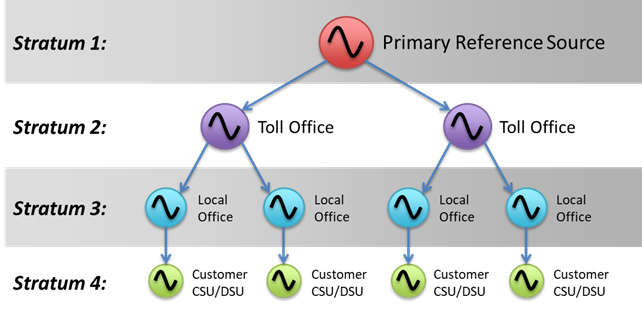
Four levels were defined initially. While the definitions apply to “clocks”, the stratum levels basically define the stability and performance of the oscillator within the clock. The clock hierarchy is shown in the following diagram:

- Stratum 1 has the ultimate stability. This is the “heartbeat” for the entire telecoms network, and when first introduced, it was expected that an operator would only have one or two Statum 1 clocks in the network. Typically this requires a good Caesium beam tube implementation.
- Stratum 2 is the next level down, and were dedicated distribution units housed in central office locations within a city or region. A Stratum 2 clock requires a very good OCXO or Rb oscillator.
- Stratum 3 is the next level down in the distribution network. These clocks were found within networking equipment, such as SONET add-drop muxes. The oscillator type for stratum 3 is usually a TCXO.
- Stratum 4 is the end node, found in customer premise equipment such as a PABX (Private Automatic Branch Exchange) or CSU/DSU (Channel Service Unit/Data Service Unit). This required a reasonably stable quartz oscillator.
The following table summarises the performance of the four stratum levels, along with two “enhanced” clock types introduced during the SONET standards (adapted from Table 3-1 from GR-1244-CORE):
| Stratum Level | Free-Run
Frequency
Accuracy
(Note 1) | Holdover
Stability
(Note 2) | Minimum Pull-in
and Hold-in
Range
(Note 3) | Filtering
Bandwidth | Output Phase
Transients |
|---|
| 1 | ±1×10-11 | N/A | N/A | N/A | N/A |
|---|
| 2 | ±1.6×10⁻⁸ | ±1×10⁻¹⁰/day | ±1.6×10⁻⁸ | 0.001 Hz | MTIE ≤ 150 ns |
|---|
| 3E | ±4.6×10⁻⁶ | ±1.2×10⁻⁸
(first 24 hours) | ±4.6×10⁻⁶ | 0.001 Hz | MTIE ≤ 150 ns |
|---|
| 3 | ±4.6×10⁻⁶ | <255 slips
(first 24 hours) | ±4.6×10⁻⁶ | 3 Hz | MTIE ≤ 1.0 μs |
|---|
| 4E (Note 4) | ±32×10-6 | N/A | ±32×10-6 | None | MTIE ≤ 1.0 μs |
|---|
| 4 (Note 4) | ±32×10-6 | N/A | ±32×10-6 | None | N/A |
|---|
Note 1: Free-run accuracy represents the long-term (20 years) limit on the maximum frequency deviation from the nominal frequency with no outside frequency reference (Free-run Mode).
Note 2: Holdover stability represents the maximum change in the clock frequency over time after the loss of all frequency references (Holdover Mode).
Note 3: Pull-in range is a measure of the maximum input frequency deviation from the nominal clock rate that can be overcome by a clock to pull itself into synchronization with a reference signal.
Note 4: The primary difference between Stratum 4E and Stratum 4 clocks is that Stratum 4E clocks are required to support clock hardware and timing reference protection switching capabilities.
How do these relate to the ITU-T clock types?
During the development of the SDH standards in the 1990s, the ITU-T took the standards for the regional systems (the ANSI standards for N. America, and the ETSI standards for Europe) and merged them into a single set of documents.
There are some very slight differences, but broadly speaking:
- Stratum 1 is equivalent to the G.811 Primary Reference Clock
- Stratum 2 is equivalent to the G.812 Type II Clock
- Stratum 3E is equivalent to the G.812 Type III Clock
- Stratum 3 is equivalent to the G.813 Option II clock (and later, the G.8262 Option II clock)

